Tag Archives: IR receiver

Video: AnalysIR Demo Batch Infrared Decoding

Here we show a screen capture demonstration of the ‘Batch Decoding’ feature of AnalysIR. We show Infrared signals from 4 different Air Conditioners and how we can load them into AnalysIR and execute a batch decode of all of the signals in one easy step. Included are signals from Panasonic, Vestel, Fujitsu & Daikin

Continue reading Video: AnalysIR Demo Batch Infrared Decoding

Controlling Chigo Air Conditioner via Infrared from smart phone

Anyone who has tried  controlling an Air Conditioner unit using an Arduino, USB IR Toy, RPi or any MCU will know how difficult it can be to record the longer infrared signals they use. Typical TV systems use IR signals circa 32 bits long, while this Chigo AC unit uses a signal with 197 marks & spaces (or 97 data bits). One of our users, Sertunc – from Istanbul in Turkey, reported his success using AnalysIR to easily record the signal timings for his AC unit and sent us the details along with some nice photos. After testing the validity of the recorded signals using an Arduino, he then set about loading the signals onto his Samsung smart phone (models S4, s4 mini, S5 and more supported). This was helped by installing the free ‘Samsung IR – Universal Remote‘ app onto his phone via Google Play.

Samsung IR Remote app Samsung IR Remote app

Continue reading Controlling Chigo Air Conditioner via Infrared from smart phone

Poor maker’s Infrared receiver #2

Our recent post about the silver bullet IR receiver proved very popular and we promised that we would follow-up with another variant of the poor maker’s Infrared receiver. This time we are using an IR Led (emitter), 2 resistors and any standard Arduino. You will also need to download the Arduino code provided below, compile and upload it. One of the most common problems encountered when trying to decode IR signals is that makers don’t always have the appropriate IR receiver for the job in hand or have to wait for one to be delivered by mail. Here we present an affordable method to allow you to use any IR emitter (LED) as a receiver and as a bonus we are publishing the Arduino code to make it all work.

Circuit Diagram: Poor maker's IR Receiver
Circuit Diagram: Poor maker’s IR Receiver

Continue reading Poor maker’s Infrared receiver #2

‘Silver bullet’ – the Oscilloscope Infrared Receiver

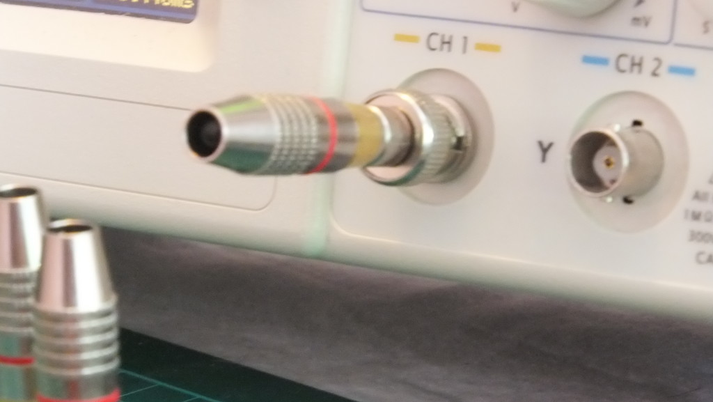
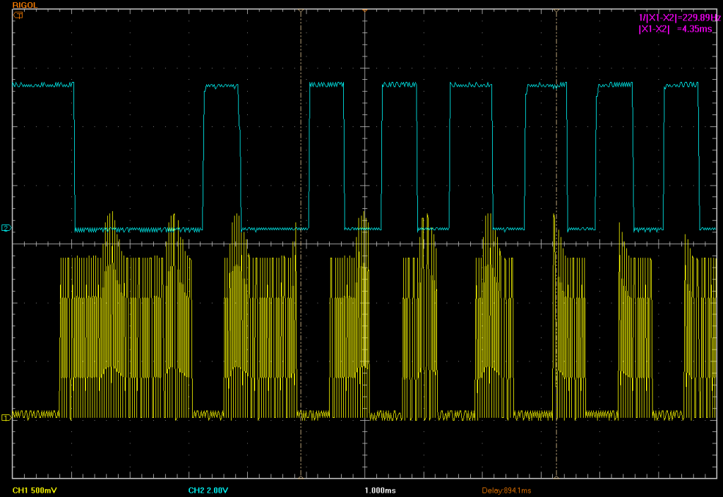
A while ago we came across a website on infrared remote controls which suggested a simple way to view IR signals using an Oscilloscope. The idea is to use a standard IR Led mounted into a BNC/RCA plug using a spare channel  making an Oscilloscope infrared receiver. So we set about ordering the connectors, which arrived in the post today. Another way of looking at this device is as a ‘poor-mans’ IR receiver, but if you have an Oscilloscope to plug it into then maybe you are not so poor after all.

Silver Bullet - Infrared Receiver connected to Channel 1
Silver Bullet – Infrared Receiver connected to Channel 1

Continue reading ‘Silver bullet’ – the Oscilloscope Infrared Receiver

Infrared Receivers – signal lag and distortion

Many electronics enthusiasts will be familiar with how Infrared receivers demodulate IR signals. In this post we show a visualisation of the time lag and distortion of the signals as they pass through the IR receiver for demodulation and noise filtering.  Most DIY projects use the raw timings from the IR receiver to decode individual signals. However, not many will be aware that IR receivers can distort the signal timings by significant amounts. Fortunately, common IR decoders take this into account and compensate for timing distortions introduced by infrared demodulators / receivers.

Infrared Signal, Modulated & De-modulated

Continue reading Infrared Receivers – signal lag and distortion

Arduino: 10 common pitfalls with Infrared Remote Control

Arduino: 10 common pitfalls with Infrared Remote Control

Over the last few months we have been regular contributors to the Arduino and other forums, answering questions about Infrared remote control projects. It became apparent that beginners typically trip up on many common ‘pitfalls’. So we decided to list off our ‘Top 10’.


Continue reading Arduino: 10 common pitfalls with Infrared Remote Control

Testing AnalysIR with a custom PCB

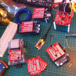
Here are some photos we captured, of a sample of our MCU test rigs and custom PCB for AnalysIR.

AnalysIRtestrigs
A sample of our test rigs for AnalysIR

The photo above shows some of our test setup for Arduino, Raspberry Pi, TI MSP430 LaunchPad and the (big) baby of them all the USB IR Toy. The small red custom PCBs are ones we had made via Elecrow which worked out great. So instead of just using  solderless breadboards we now plug these ‘half shields’ directly into the Arduino header, or in the case of the RPi using a ribbon cable. The USB IR Toy already has the IR receivers on board and doesn’t require this PCB.

We should also be able to hook up the LaunchPad to this board using headers. So once we receive the full set of headers, we ordered on-line, we will have all our test setups much neater and more reliable. Previously, we used solderless breadboards, as can be seen in the photo attached to the LaunchPad. Continue reading Testing AnalysIR with a custom PCB

Update: Campaign reaches 100 backers, RPi & News

We have now reached 100 unique backers for AnalysIR and we would like to thank you all for your generous support & welcome our latest backers. In particular, we would like to give a special thanks to those who made donations without perks.

And now for the News:

  • The components for the Starter Kits have arrived as expected; the envelopes are already printed with addresses taken from IGG & we plan to drop them off at the Post Office sometime on Monday. Hopefully, most people will have received them before AnalysIR is released to backers (circa: 9th September, which allows1 week after the campaign ends to eliminate as many glitches as possible). Remember, to get the full use of AnalysIR you will need the components in Kit A, as a minimum. However, just having an IR receiver is sufficient.(+ of course an Arduino).
    So far, everyone has chosen ‘Kit F’, which is probably a good idea.
  • Regarding the Raspberry Pi ‘stretch goal’, it looks like we may not reach this goal, based on the current trajectory. However, we decided to purchase a Pi with the IGG (aka your) funds released to date & it arrived yesterday. After a lot of ‘wasted’ time trying to get it set up without a display we eventually succeeded. So today we had a go at porting our Arduino code over to the RPi. For the initial attempt, we have decided to use the WiringPi library & we have good success so far. So here is an exported trace image of the first successful NEC IR signal decoded by AnalysIR from a Raspberry Pi.
    SignalTraceImage
    First successful NEC IR signal decoded by AnalysIR from a Raspberry Pi

    use CTRL+
    On the top you can see the same IR signal recorded directly by AnalysIR at the same time (via 2 different IR receivers – one connected to an Arduino & the other connected to an RPi pin)

  • We haven’t fully finished with the RPi coding yet & there are some minor glitches, but we are happy with it as a first attempt. At the moment we are using interrupts & are only dumping the information to a terminal screen via a network connection & then manually pasting the output into AnalysIR’s import facility. We have to do some further study to see how we can best get ‘serial’ data from the RPi to the Windows PC. The simple solution is to use a USB serial adapter connected to the Rx/Tx pins of the RPi, but given it already has an Ethernet port we are going to investigate if a more elegant solution is feasible.

That’s all for now……… Next week = Documentation update

Update: Kits, IR Compression, Serial Hack etc….

As we are approaching the last 10 days of the campaign we would like to share the following updates:

● Today we were informed that the kit components were shipped via UPS to us here in Dublin. Hopefully, they will arrive within a few days, which means we should be able to start posting them out over the weekend or early next week.

● We have been busy this week with preparing the Windows installation package and it seems to be going well – so far.
● We also improved the Arduino code and increased the effective RAM available for AnalysIR.
● We have also integrated the IR modulation measurement into the GUI and it works well with the Modulation frequency being updated ‘at least’ once per IR signal. As we mentioned previously, we have not seen an example of IR modulation frequency being measured on an Arduino before, and particularly not simultaneous with IR decoding.
● We have also added support for compression of IR when importing or exporting in Global Cache format.
● Yesterday we had an interesting experience with the Arduino. As we were swapping out one IR receiver and held the signal line in the hand – a signal received by AnalysIR. We inspected the signal and it seemed to be pretty consistent, so it was analysed quickly using excel and it turned out (not surprisingly) to be mains hum which in this part of the world has a frequency of 50Hz (vs 60Hz elsewhere). That then got me thinking about the following hack!
● We then tested sending a series of serial signals from another Arduino into the IR rx pin and voila the serial trace appeared in the display of AnalysIR. We successfully tested up to 38400 BAUD and bit higher. So even though we do not plan to ‘officially’ support serial protocols at this time, it means that you could potentially use AnalysIR as a pseudo Serial analyzer or even a basic digital signal/logic analyzer of sorts. The limit would be somewhere between 40-50kHz, on a 16MHz Arduino. Not bad a hack before release  🙂

● We have recently come across several new IR protocols including:
Denon
Motorola
Samsung
Daewoo
Japanese Code

– To date we have completed all the investigations needed to decode them and add them to AnalysIR. However, we will have to defer this until after the initial release has settled down & we can get reliable source signals to verify against. Once we complete these new signals we will be heading towards an even more comprehensive list of supported protocols.


……stay tuned

Infrared Component Kits

We have decided to offer a small number of Infrared Component Kits to help users of AnalysIR get started quickly. As a minimum you will require 1 IR receiver to use AnalysIR, plus we highly recommend the ‘IR Learner’ below if you also want to measure modulation frequency.

(Note: This is an updated copy of the original document from the crowd-funding campaign. The original document can be found here.)

IR receivers/emitter in Infrared Component Kits:

Model Frequency Description Gain Typical Application
TSSP4038 38kHz 1 x IR receiver Fixed Gain Barrier + AnalysIR
TSMP58000 20 -> 60kHz 1 x IR receiver Learner + AnalysIR
TSOP4436 36kHz 1 x IR receiver AGC 4 RC5/6
TSOP34438 38kHz 1 x IR receiver AGC 4 NEC
TSOP4840 40kHz 1 x IR receiver AGC 2 SONY
TSOP2256 56kHz 1 x IR receiver AGC 2 RCA
TSAL6100 All 1 x IR emitter IR LED transmitter

AGC 2: Standard Applications
AGC 4: Very Noisy Environment

Kits do not include AnalysIR

Select one or more kits from the following:

Item Kit A Kit B Kit C Kit D Kit E Kit F
TSSP4038 Y Y Y Y Y Y
TSMP58000 Y Y Y Y Y Y
TSOP4436 Y Y Y Y
TSOP34438 Y Y Y Y
TSOP4840 Y Y
TSOP34156 Y
TSAL6100 Y Y Y Y Y
Bonus Gift see 11
below
Y Y Y Y Y Y
Shipping see 9
below
Y Y Y Y Y Y
Student Tip Y Y Y Y Y Y
Perk Price $8 $10 $10 $12 $13 $15

 Y = Included

Instructions:

  1. Select the kit you want based on the items included
  2. For example, Kit A contains 1 x TSSP4038, 1 x TSMP58000, plus shipping (see 9 below) and a small tip/gratuity for the student.
  3. Then purchase the kit or kits you want by contributing the relevant cost (or sum for multiple kits)
  4. To purchase Kit A just make  an $8 payment  via the PayPal button on this page. To purchase multiple kits just make one contribution to the same perk for the total amount.
  5. If you select Kit B or Kit C then include  a message on PayPal to clarify which perk you want.
  6. These component Kits do not include AnalysIR.
  7. Cost increased (Sep 2014) due to increase in postage.
  8. TSOP4438 replaced with more modern TSOP34438.
  9. Shipping: is included in price above, provided you are also buying AnalysIR or have bought AnalysIR previously. Otherwise, add $5 to the prices above (once only) for worldwide shipping.
  10. Delivery, usually takes from 5->10 working days. There may be some exceptions to this – depending on location.
  11. Bonus gift: We also include a selection of useful components, with all kits, to help with your IR projects. (2 x NPN + 8 x resistors … enough to complete a good Infrared emitter circuit for longer range)

Notes:

  1. Please feel free to order these parts directly your-self. We won’t be offended in any way. We are not offering these to make any $$$ at all. In fact it is much less work for us if backers have or supply their own components.
  2. Kit A, B or C is more than adequate for most users.
  3. Standard shipping worldwide for owners of AnalysIR is included, Otherwise add an extra $5, as per Instruction 9 above.  Postage is not tracked or insured. Unfortunately, we cannot provide any replacements for items mislaid in the post or delivery failures. Due to the low value, we do not expect that there would be customs charges etc.  and if there are any you will have to cover this cost.
  4. We have included a small tip/gratuity for the student who has agreed to pack & post these perks.
  5. This perk is intended as a quick start aid for backers.
  6. These perks will be posted from Dublin, Ireland and typically take 5-10 working days depending on worldwide destination.
  7. You can select multiple kits.
  8. All kit IR components are from Vishay, who are a leading supplier of high quality components. We use them all the time for IR components.
  9. We have allowed for the Sales Tax, IGG, PayPal, Currency & inward shipping charges which will be levied on us for these components.
  10. We reserve the right, at our sole discretion, to alter or replace any component if it is not available when we order them. However, we will do our best to match functionality as much as is reasonable. Hopefully this won’t be an issue.
  11. We have not included any Arduinos as they are freely available online. Many of these kit components are not easily available in quantities of 1, without excessive mark-ups, high minimum orders or postage.
  12. Shipping will be to PayPal registered address. (Let us know, immediately, if you want it sent to an alternative address)
  13. Use the Contact Form to contact us, directly.

E.&O.E.