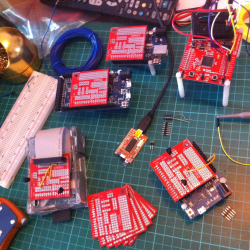
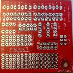
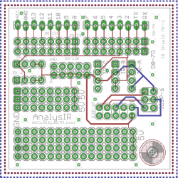
Here are some photos we captured, of a sample of our MCU test rigs and custom PCB for AnalysIR.

The photo above shows some of our test setup for Arduino, Raspberry Pi, TI MSP430 LaunchPad and the (big) baby of them all the USB IR Toy. The small red custom PCBs are ones we had made via Elecrow which worked out great. So instead of just using solderless breadboards we now plug these ‘half shields’ directly into the Arduino header, or in the case of the RPi using a ribbon cable. The USB IR Toy already has the IR receivers on board and doesn’t require this PCB.
We should also be able to hook up the LaunchPad to this board using headers. So once we receive the full set of headers, we ordered on-line, we will have all our test setups much neater and more reliable. Previously, we used solderless breadboards, as can be seen in the photo attached to the LaunchPad.

(Click for Higher resolution image)
We designed these boards especially for AnalysIR to plug directly into the header pins on the Arduino and also to take a ribbon cable from the RPi and accidently it also worked for headers from the LaunchPad. The PCB has a full set of pins available for the Arduino headers D0-13, GND and AREF. 5V is supplied via the ICSP 6 pin header. Each of these Arduino header pins have 2 adjacent connected holes. There are ample GND & 5V points throughout the PCB and there are 2 areas for prototyping. We have also included 5 sets of 4 pin headers to accept the various pinouts of the most popular IR receivers & learners, wired into pins 2 & 3 for AnalysIR. These also serve to provide additional test points for when we have to power up the Oscilloscope or Logic Analyzer.
You may have noticed that we leave the full leads on the IR receivers when soldering in. This is because we may want to replace then over time and it’s easier for us this way when desoldering.

(Could be improved)
The larger of the 2 prototyping areas accepts headers from the RPi & LaunchPad, but we have to solder in the wires to make the connections for the IR receivers. Result = life is a lot easier testing AnalysIR these days and much faster setting things up.
We also placed a 10 pin ICSP header area on the PCB connected to the 6 pin ICSP Header as a bonus because our AVR programmer has a 10 pin output and cable, but the Arduino has only a 6 pin header. Although this is not related to AnalysIR it was a good bonus feature for us on other products/projects.
At US$15 for 10 5x5cm boards including shipping and delivered in 20 days this was a great buy. So a big thumbs up for Elecrow. They also allow a choice of colour and sent us a photo of the boards once they were manufactured, which is an extra charge from similar suppliers. The PCB service from Elecrow is available here.
We are not connected with Elecrow, just a happy customer.
One thought on “Testing AnalysIR with a custom PCB”